This is the multi-page printable view of this section. Click here to print.
Cloud Platforms
- 1: Akamai
- 2: AWS
- 3: Azure
- 4: CloudStack
- 5: DigitalOcean
- 6: Exoscale
- 7: GCP
- 8: Hetzner
- 9: Kubernetes
- 10: Nocloud
- 11: OpenStack
- 12: Oracle
- 13: Scaleway
- 14: UpCloud
- 15: Vultr
1 - Akamai
Creating a Talos Linux Cluster on Akamai Connected Cloud via the CLI
This guide will demonstrate how to create a highly available Kubernetes cluster with one worker using the Akamai Connected Cloud provider.
Akamai Connected Cloud has a very well-documented REST API, and an open-source CLI tool to interact with the API which will be used in this guide.
Make sure to follow installation and authentication instructions for the linode-cli tool.
jq and talosctl also needs to be installed
Upload image
Download the Akamai image akamai-amd64.raw.gz from Image Factory.
Upload the image
export REGION=us-ord

linode-cli image-upload --region ${REGION} --label talos akamai-amd64.raw.gz
Create a Load Balancer
export REGION=us-ord

linode-cli nodebalancers create --region ${REGION} --no-defaults --label talos
export NODEBALANCER_ID=$(linode-cli nodebalancers list --label talos --format id --text --no-headers)
linode-cli nodebalancers config-create --port 443 --protocol tcp --check connection ${NODEBALANCER_ID}
Create the Machine Configuration Files
Using the IP address (or DNS name, if you have created one) of the load balancer, generate the base configuration files for the Talos machines. Also note that the load balancer forwards port 443 to port 6443 on the associated nodes, so we should use 443 as the port in the config definition:
export NODEBALANCER_IP=$(linode-cli nodebalancers list --label talos --format ipv4 --text --no-headers)

talosctl gen config talos-kubernetes-akamai https://${NODEBALANCER_IP} --with-examples=false
Create the Linodes
Create the Control Plane Nodes
Although root passwords are not used by Talos, Linode requires that a root password be associated with a linode during creation.
Run the following commands to create three control plane nodes:
export IMAGE_ID=$(linode-cli images list --label talos --format id --text --no-headers)
export NODEBALANCER_ID=$(linode-cli nodebalancers list --label talos --format id --text --no-headers)
export NODEBALANCER_CONFIG_ID=$(linode-cli nodebalancers configs-list ${NODEBALANCER_ID} --format id --text --no-headers)
export REGION=us-ord
export LINODE_TYPE=g6-standard-4
export ROOT_PW=$(pwgen 16)

for id in $(seq 3); do
  linode_label="talos-control-plane-${id}"

  # create linode

  linode-cli linodes create  \
    --no-defaults \
    --root_pass ${ROOT_PW} \
    --type ${LINODE_TYPE} \
    --region ${REGION} \
    --image ${IMAGE_ID} \
    --label ${linode_label} \
    --private_ip true \
    --tags talos-control-plane \
    --group "talos-control-plane" \
    --metadata.user_data "$(base64 -i ./controlplane.yaml)"

  # change kernel to "direct disk"
  linode_id=$(linode-cli linodes list --label ${linode_label} --format id --text --no-headers)
  confiig_id=$(linode-cli linodes configs-list ${linode_id} --format id --text --no-headers)
  linode-cli linodes config-update ${linode_id} ${confiig_id} --kernel "linode/direct-disk"

  # add machine to nodebalancer
  private_ip=$(linode-cli linodes list --label ${linode_label} --format ipv4 --json | jq -r ".[0].ipv4[1]")
  linode-cli nodebalancers node-create ${NODEBALANCER_ID}  ${NODEBALANCER_CONFIG_ID}  --label ${linode_label} --address ${private_ip}:6443
done
Create the Worker Nodes
Although root passwords are not used by Talos, Linode requires that a root password be associated with a linode during creation.
Run the following to create a worker node:
export IMAGE_ID=$(linode-cli images list --label talos --format id --text --no-headers)
export REGION=us-ord
export LINODE_TYPE=g6-standard-4
export LINODE_LABEL="talos-worker-1"
export ROOT_PW=$(pwgen 16)

linode-cli linodes create  \
    --no-defaults \
    --root_pass ${ROOT_PW} \
    --type ${LINODE_TYPE} \
    --region ${REGION} \
    --image ${IMAGE_ID} \
    --label ${LINODE_LABEL} \
    --private_ip true \
    --tags talos-worker \
    --group "talos-worker" \
    --metadata.user_data "$(base64 -i ./worker.yaml)"

linode_id=$(linode-cli linodes list --label ${LINODE_LABEL} --format id --text --no-headers)
config_id=$(linode-cli linodes configs-list ${linode_id} --format id --text --no-headers)
linode-cli linodes config-update ${linode_id} ${config_id} --kernel "linode/direct-disk"
Bootstrap Etcd
Set the endpoints and nodes:
export LINODE_LABEL=talos-control-plane-1
export LINODE_IP=$(linode-cli linodes list --label ${LINODE_LABEL} --format ipv4 --json | jq -r ".[0].ipv4[0]")
talosctl --talosconfig talosconfig config endpoint ${LINODE_IP}
talosctl --talosconfig talosconfig config node ${LINODE_IP}
Bootstrap etcd:
talosctl --talosconfig talosconfig bootstrap
Retrieve the kubeconfig
At this point, we can retrieve the admin kubeconfig by running:
talosctl --talosconfig talosconfig kubeconfig .
We can also watch the cluster bootstrap via:
talosctl --talosconfig talosconfig health
Alternatively, we can also watch the node overview, logs and real-time metrics dashboard via:
talosctl --talosconfig talosconfig dashboard
2 - AWS
Creating a Cluster via the AWS CLI
In this guide we will create an HA Kubernetes cluster with 3 control plane nodes across 3 availability zones. You should have an existing AWS account and have the AWS CLI installed and configured. If you need more information on AWS specifics, please see the official AWS documentation.
To install the dependencies for this tutorial you can use homebrew on macOS or Linux:
brew install siderolabs/tap/talosctl kubectl jq curl xz
If you would like to create infrastructure via terraform or opentofu please see the example in the contrib repository.
Note: this guide is not a production set up and steps were tested in
bashandzshshells.
Create AWS Resources
We will be creating a control plane with 3 Ec2 instances spread across 3 availability zones. It is recommended to not use the default VPC so we will create a new one for this tutorial.
Change to your desired region and CIDR block and create a VPC:
Make sure your subnet does not overlap with
10.244.0.0/16or10.96.0.0/12the default pod and services subnets in Kubernetes.
AWS_REGION="us-west-2"
IPV4_CIDR="10.1.0.0/18"
VPC_ID=$(aws ec2 create-vpc \
    --cidr-block $IPV4_CIDR \
    --output text --query 'Vpc.VpcId')
Create the Subnets
Create 3 smaller CIDRs to use for each subnet in different availability zones. Make sure to adjust these CIDRs if you changed the default value from the last command.
IPV4_CIDRS=( "10.1.0.0/22" "10.1.4.0/22" "10.1.8.0/22" )
Next create a subnet in each availability zones.
Note: If you’re using zsh you need to run
setopt KSH_ARRAYSto have arrays referenced properly.
CIDR=0
declare -a SUBNETS
AZS=($(aws ec2 describe-availability-zones \
    --query 'AvailabilityZones[].ZoneName' \
    --filter "Name=state,Values=available" \
    --output text | tr -s '\t' '\n' | head -n3))

for AZ in ${AZS[@]}; do
        SUBNETS[$CIDR]=$(aws ec2 create-subnet \
            --vpc-id $VPC_ID \
            --availability-zone $AZ \
            --cidr-block ${IPV4_CIDRS[$CIDR]} \
            --query 'Subnet.SubnetId' \
            --output text)
        aws ec2 modify-subnet-attribute \
            --subnet-id ${SUBNETS[$CIDR]} \
            --private-dns-hostname-type-on-launch resource-name
        echo ${SUBNETS[$CIDR]}
        ((CIDR++))
done
Create an internet gateway and attach it to the VPC:
IGW_ID=$(aws ec2 create-internet-gateway \
    --query 'InternetGateway.InternetGatewayId' \
    --output text)

aws ec2 attach-internet-gateway \
    --vpc-id $VPC_ID \
    --internet-gateway-id $IGW_ID

ROUTE_TABLE_ID=$(aws ec2 describe-route-tables \
        --filters "Name=vpc-id,Values=$VPC_ID" \
        --query 'RouteTables[].RouteTableId' \
        --output text)

aws ec2 create-route \
    --route-table-id $ROUTE_TABLE_ID \
    --destination-cidr-block 0.0.0.0/0 \
    --gateway-id $IGW_ID
Official AMI Images
Official AMI image ID can be found in the cloud-images.json file attached to the Talos release.
AMI=$(curl -sL https://github.com/siderolabs/talos/releases/download/v1.8.0/cloud-images.json | \
    jq -r '.[] | select(.region == "'$AWS_REGION'") | select (.arch == "amd64") | .id')
echo $AMI
If using the official AMIs, you can skip to Creating the Security group
Create your own AMIs
The use of the official Talos AMIs are recommended, but if you wish to build your own AMIs, follow the procedure below.
Create the S3 Bucket
aws s3api create-bucket \
    --bucket $BUCKET \
    --create-bucket-configuration LocationConstraint=$AWS_REGION \
    --acl private
Create the vmimport Role
In order to create an AMI, ensure that the vmimport role exists as described in the official AWS documentation.
Note that the role should be associated with the S3 bucket we created above.
Create the Image Snapshot
First, download the AWS image from Image Factory:
curl -L https://factory.talos.dev/image/376567988ad370138ad8b2698212367b8edcb69b5fd68c80be1f2ec7d603b4ba/v1.8.0/aws-amd64.raw.xz | xz -d > disk.raw
Copy the RAW disk to S3 and import it as a snapshot:
aws s3 cp disk.raw s3://$BUCKET/talos-aws-tutorial.raw
$SNAPSHOT_ID=$(aws ec2 import-snapshot \
    --region $REGION \
    --description "Talos kubernetes tutorial" \
    --disk-container "Format=raw,UserBucket={S3Bucket=$BUCKET,S3Key=talos-aws-tutorial.raw}" \
    --query 'SnapshotId' \
    --output text)
To check on the status of the import, run:
aws ec2 describe-import-snapshot-tasks \
    --import-task-ids
Once the SnapshotTaskDetail.Status indicates completed, we can register the image.
Register the Image
AMI=$(aws ec2 register-image \
    --block-device-mappings "DeviceName=/dev/xvda,VirtualName=talos,Ebs={DeleteOnTermination=true,SnapshotId=$SNAPSHOT_ID,VolumeSize=4,VolumeType=gp2}" \
    --root-device-name /dev/xvda \
    --virtualization-type hvm \
    --architecture x86_64 \
    --ena-support \
    --name talos-aws-tutorial-ami \
    --query 'ImageId' \
    --output text)
We now have an AMI we can use to create our cluster.
Create a Security Group
SECURITY_GROUP_ID=$(aws ec2 create-security-group \
    --vpc-id $VPC_ID \
    --group-name talos-aws-tutorial-sg \
    --description "Security Group for EC2 instances to allow ports required by Talos" \
    --query 'GroupId' \
    --output text)
Using the security group from above, allow all internal traffic within the same security group:
aws ec2 authorize-security-group-ingress \
    --group-id $SECURITY_GROUP_ID \
    --protocol all \
    --port 0 \
    --source-group $SECURITY_GROUP_ID
Expose the Talos (50000) and Kubernetes API.
Note: This is only required for the control plane nodes. For a production environment you would want separate private subnets for worker nodes.
aws ec2 authorize-security-group-ingress \
    --group-id $SECURITY_GROUP_ID \
    --ip-permissions \
        IpProtocol=tcp,FromPort=50000,ToPort=50000,IpRanges="[{CidrIp=0.0.0.0/0}]" \
        IpProtocol=tcp,FromPort=6443,ToPort=6443,IpRanges="[{CidrIp=0.0.0.0/0}]" \
    --query 'SecurityGroupRules[].SecurityGroupRuleId' \
    --output text
We will bootstrap Talos with a MachineConfig via user-data it will never be exposed to the internet without certificate authentication.
We enable KubeSpan in this tutorial so you need to allow inbound UDP for the Wireguard port:
aws ec2 authorize-security-group-ingress \
    --group-id $SECURITY_GROUP_ID \
    --ip-permissions \
        IpProtocol=tcp,FromPort=51820,ToPort=51820,IpRanges="[{CidrIp=0.0.0.0/0}]" \
    --query 'SecurityGroupRules[].SecurityGroupRuleId' \
    --output text
Create a Load Balancer
The load balancer is used for a stable Kubernetes API endpoint.
LOAD_BALANCER_ARN=$(aws elbv2 create-load-balancer \
    --name talos-aws-tutorial-lb \
    --subnets $(echo ${SUBNETS[@]}) \
    --type network \
    --ip-address-type ipv4 \
    --query 'LoadBalancers[].LoadBalancerArn' \
    --output text)

LOAD_BALANCER_DNS=$(aws elbv2 describe-load-balancers \
    --load-balancer-arns $LOAD_BALANCER_ARN \
    --query 'LoadBalancers[].DNSName' \
    --output text)
Now create a target group for the load balancer:
TARGET_GROUP_ARN=$(aws elbv2 create-target-group \
    --name talos-aws-tutorial-tg \
    --protocol TCP \
    --port 6443 \
    --target-type instance \
    --vpc-id $VPC_ID \
    --query 'TargetGroups[].TargetGroupArn' \
    --output text)

LISTENER_ARN=$(aws elbv2 create-listener \
    --load-balancer-arn $LOAD_BALANCER_ARN \
    --protocol TCP \
    --port 6443 \
    --default-actions Type=forward,TargetGroupArn=$TARGET_GROUP_ARN \
    --query 'Listeners[].ListenerArn' \
    --output text)
Create the Machine Configuration Files
We will create a machine config patch to use the AWS time servers. You can create additional patches to customize the configuration as needed.
cat <<EOF > time-server-patch.yaml
machine:
  time:
    servers:
      - 169.254.169.123
EOF
Using the DNS name of the loadbalancer created earlier, generate the base configuration files for the Talos machines.
talosctl gen config talos-k8s-aws-tutorial https://${LOAD_BALANCER_DNS}:6443 \
    --with-examples=false \
    --with-docs=false \
    --with-kubespan \
    --install-disk /dev/xvda \
    --config-patch '@time-server-patch.yaml'
Note that the generated configs are too long for AWS userdata field if the
--with-examplesand--with-docsflags are not passed.
Create the EC2 Instances
Note: There is a known issue that prevents Talos from running on T2 instance types. Please use T3 if you need burstable instance types.
Create the Control Plane Nodes
declare -a CP_INSTANCES
INSTANCE_INDEX=0
for SUBNET in ${SUBNETS[@]}; do
    CP_INSTANCES[${INSTANCE_INDEX}]=$(aws ec2 run-instances \
        --image-id $AMI \
        --subnet-id $SUBNET \
        --instance-type t3.small \
        --user-data file://controlplane.yaml \
        --associate-public-ip-address \
        --security-group-ids $SECURITY_GROUP_ID \
        --count 1 \
        --tag-specifications "ResourceType=instance,Tags=[{Key=Name,Value=talos-aws-tutorial-cp-$INSTANCE_INDEX}]" \
        --query 'Instances[].InstanceId' \
        --output text)
    echo ${CP_INSTANCES[${INSTANCE_INDEX}]}
    ((INSTANCE_INDEX++))
done
Create the Worker Nodes
For the worker nodes we will create a new launch template with the worker.yaml machine configuration and create an autoscaling group.
WORKER_LAUNCH_TEMPLATE_ID=$(aws ec2 create-launch-template \
    --launch-template-name talos-aws-tutorial-worker \
    --launch-template-data '{
        "ImageId":"'$AMI'",
        "InstanceType":"t3.small",
        "UserData":"'$(base64 -w0 worker.yaml)'",
        "NetworkInterfaces":[{
            "DeviceIndex":0,
            "AssociatePublicIpAddress":true,
            "Groups":["'$SECURITY_GROUP_ID'"],
            "DeleteOnTermination":true
        }],
        "BlockDeviceMappings":[{
            "DeviceName":"/dev/xvda",
            "Ebs":{
                "VolumeSize":20,
                "VolumeType":"gp3",
                "DeleteOnTermination":true
            }
        }],
        "TagSpecifications":[{
            "ResourceType":"instance",
            "Tags":[{
          "Key":"Name",
          "Value":"talos-aws-tutorial-worker"
          }]
        }]}' \
    --query 'LaunchTemplate.LaunchTemplateId' \
    --output text)
aws autoscaling create-auto-scaling-group \
    --auto-scaling-group-name talos-aws-tutorial-worker \
    --min-size 1 \
    --max-size 3 \
    --desired-capacity 1 \
    --availability-zones $(echo ${AZS[@]}) \
    --target-group-arns $TARGET_GROUP_ARN \
    --launch-template "LaunchTemplateId=${WORKER_LAUNCH_TEMPLATE_ID}" \
    --vpc-zone-identifier $(echo ${SUBNETS[@]} | tr ' ' ',')
Configure the Load Balancer
Now, using the load balancer target group’s ARN, and the PrivateIpAddress from the controlplane instances that you created :
for INSTANCE in ${CP_INSTANCES[@]}; do
    aws elbv2 register-targets \
    --target-group-arn $TARGET_GROUP_ARN \
    --targets Id=$(aws ec2 describe-instances \
        --instance-ids $INSTANCE \
        --query 'Reservations[].Instances[].InstanceId' \
        --output text)
done
Export the talosconfig file
Export the talosconfig file so commands sent to Talos will be authenticated.
export TALOSCONFIG=$(pwd)/talosconfig
Bootstrap etcd
WORKER_INSTANCES=( $(aws autoscaling \
    describe-auto-scaling-instances \
    --query 'AutoScalingInstances[?AutoScalingGroupName==`talos-aws-tutorial-worker`].InstanceId' \
    --output text) )
Set the endpoints (the control plane node to which talosctl commands are sent) and nodes (the nodes that the command operates on):
talosctl config endpoints $(aws ec2 describe-instances \
    --instance-ids ${CP_INSTANCES[*]} \
    --query 'Reservations[].Instances[].PublicIpAddress' \
    --output text)

talosctl config nodes $(aws ec2 describe-instances \
    --instance-ids $(echo ${CP_INSTANCES[1]}) \
    --query 'Reservations[].Instances[].PublicIpAddress' \
    --output text)
Bootstrap etcd:
talosctl bootstrap
You can now watch as your cluster bootstraps, by using
talosctl health
This command will take a few minutes for the nodes to start etcd, reach quarom and start the Kubernetes control plane.
You can also watch the performance of a node, via:
talosctl dashboard
Retrieve the kubeconfig
When the cluster is healthy you can retrieve the admin kubeconfig by running:
talosctl kubeconfig .
export KUBECONFIG=$(pwd)/kubeconfig
And use standard kubectl commands.
kubectl get nodes
Cleanup resources
If you would like to delete all of the resources you created during this tutorial you can run the following commands.
aws elbv2 delete-listener --listener-arn $LISTENER_ARN
aws elbv2 delete-target-group --target-group-arn $TARGET_GROUP_ARN
aws elbv2 delete-load-balancer --load-balancer-arn $LOAD_BALANCER_ARN

aws autoscaling update-auto-scaling-group \
    --auto-scaling-group-name talos-aws-tutorial-worker \
    --min-size 0 \
    --max-size 0 \
    --desired-capacity 0

aws ec2 terminate-instances --instance-ids ${CP_INSTANCES[@]} ${WORKER_INSTANCES[@]} \
    --query 'TerminatingInstances[].InstanceId' \
    --output text

aws autoscaling delete-auto-scaling-group \
    --auto-scaling-group-name talos-aws-tutorial-worker \
    --force-delete

aws ec2 delete-launch-template --launch-template-id $WORKER_LAUNCH_TEMPLATE_ID

while $(aws ec2 describe-instances \
    --instance-ids ${CP_INSTANCES[@]} ${WORKER_INSTANCES[@]} \
    --query 'Reservations[].Instances[].[InstanceId,State.Name]' \
    --output text | grep -q shutting-down); do \
        echo "waiting for instances to terminate"; sleep 5s
done

aws ec2 detach-internet-gateway --vpc-id $VPC_ID --internet-gateway-id $IGW_ID
aws ec2 delete-internet-gateway --internet-gateway-id $IGW_ID

aws ec2 delete-security-group --group-id $SECURITY_GROUP_ID

for SUBNET in ${SUBNETS[@]}; do
    aws ec2 delete-subnet --subnet-id $SUBNET
done

aws ec2 delete-vpc --vpc-id $VPC_ID

rm -f controlplane.yaml worker.yaml talosconfig kubeconfig time-server-patch.yaml disk.raw
3 - Azure
Creating a Cluster via the CLI
In this guide we will create an HA Kubernetes cluster with 1 worker node. We assume existing Blob Storage, and some familiarity with Azure. If you need more information on Azure specifics, please see the official Azure documentation.
Environment Setup
We’ll make use of the following environment variables throughout the setup. Edit the variables below with your correct information.
# Storage account to use
export STORAGE_ACCOUNT="StorageAccountName"

# Storage container to upload to
export STORAGE_CONTAINER="StorageContainerName"

# Resource group name
export GROUP="ResourceGroupName"

# Location
export LOCATION="centralus"

# Get storage account connection string based on info above
export CONNECTION=$(az storage account show-connection-string \
                    -n $STORAGE_ACCOUNT \
                    -g $GROUP \
                    -o tsv)
Choose an Image
There are two methods of deployment in this tutorial.
If you would like to use the official Talos image uploaded to Azure Community Galleries by SideroLabs, you may skip ahead to setting up your network infrastructure.
Otherwise, if you would like to upload your own image to Azure and use it to deploy Talos, continue to Creating an Image.
Create the Image
First, download the Azure image from a Talos release.
Once downloaded, untar with tar -xvf /path/to/azure-amd64.tar.gz
Upload the VHD
Once you have pulled down the image, you can upload it to blob storage with:
az storage blob upload \
  --connection-string $CONNECTION \
  --container-name $STORAGE_CONTAINER \
  -f /path/to/extracted/talos-azure.vhd \
  -n talos-azure.vhd
Register the Image
Now that the image is present in our blob storage, we’ll register it.
az image create \
  --name talos \
  --source https://$STORAGE_ACCOUNT.blob.core.windows.net/$STORAGE_CONTAINER/talos-azure.vhd \
  --os-type linux \
  -g $GROUP
Network Infrastructure
Virtual Networks and Security Groups
Once the image is prepared, we’ll want to work through setting up the network. Issue the following to create a network security group and add rules to it.
# Create vnet
az network vnet create \
  --resource-group $GROUP \
  --location $LOCATION \
  --name talos-vnet \
  --subnet-name talos-subnet

# Create network security group
az network nsg create -g $GROUP -n talos-sg

# Client -> apid
az network nsg rule create \
  -g $GROUP \
  --nsg-name talos-sg \
  -n apid \
  --priority 1001 \
  --destination-port-ranges 50000 \
  --direction inbound

# Trustd
az network nsg rule create \
  -g $GROUP \
  --nsg-name talos-sg \
  -n trustd \
  --priority 1002 \
  --destination-port-ranges 50001 \
  --direction inbound

# etcd
az network nsg rule create \
  -g $GROUP \
  --nsg-name talos-sg \
  -n etcd \
  --priority 1003 \
  --destination-port-ranges 2379-2380 \
  --direction inbound

# Kubernetes API Server
az network nsg rule create \
  -g $GROUP \
  --nsg-name talos-sg \
  -n kube \
  --priority 1004 \
  --destination-port-ranges 6443 \
  --direction inbound
Load Balancer
We will create a public ip, load balancer, and a health check that we will use for our control plane.
# Create public ip
az network public-ip create \
  --resource-group $GROUP \
  --name talos-public-ip \
  --allocation-method static

# Create lb
az network lb create \
  --resource-group $GROUP \
  --name talos-lb \
  --public-ip-address talos-public-ip \
  --frontend-ip-name talos-fe \
  --backend-pool-name talos-be-pool

# Create health check
az network lb probe create \
  --resource-group $GROUP \
  --lb-name talos-lb \
  --name talos-lb-health \
  --protocol tcp \
  --port 6443

# Create lb rule for 6443
az network lb rule create \
  --resource-group $GROUP \
  --lb-name talos-lb \
  --name talos-6443 \
  --protocol tcp \
  --frontend-ip-name talos-fe \
  --frontend-port 6443 \
  --backend-pool-name talos-be-pool \
  --backend-port 6443 \
  --probe-name talos-lb-health
Network Interfaces
In Azure, we have to pre-create the NICs for our control plane so that they can be associated with our load balancer.
for i in $( seq 0 1 2 ); do
  # Create public IP for each nic
  az network public-ip create \
    --resource-group $GROUP \
    --name talos-controlplane-public-ip-$i \
    --allocation-method static


  # Create nic
  az network nic create \
    --resource-group $GROUP \
    --name talos-controlplane-nic-$i \
    --vnet-name talos-vnet \
    --subnet talos-subnet \
    --network-security-group talos-sg \
    --public-ip-address talos-controlplane-public-ip-$i\
    --lb-name talos-lb \
    --lb-address-pools talos-be-pool
done

# NOTES:
# Talos can detect PublicIPs automatically if PublicIP SKU is Basic.
# Use `--sku Basic` to set SKU to Basic.
Cluster Configuration
With our networking bits setup, we’ll fetch the IP for our load balancer and create our configuration files.
LB_PUBLIC_IP=$(az network public-ip show \
              --resource-group $GROUP \
              --name talos-public-ip \
              --query "ipAddress" \
              --output tsv)

talosctl gen config talos-k8s-azure-tutorial https://${LB_PUBLIC_IP}:6443
Compute Creation
We are now ready to create our azure nodes.
Azure allows you to pass Talos machine configuration to the virtual machine at bootstrap time via
user-data or custom-data methods.
Talos supports only custom-data method, machine configuration is available to the VM only on the first boot.
Use the steps below depending on whether you have manually uploaded a Talos image or if you are using the Community Gallery image.
Manual Image Upload
# Create availability set
az vm availability-set create \
  --name talos-controlplane-av-set \
  -g $GROUP

# Create the controlplane nodes
for i in $( seq 0 1 2 ); do
  az vm create \
    --name talos-controlplane-$i \
    --image talos \
    --custom-data ./controlplane.yaml \
    -g $GROUP \
    --admin-username talos \
    --generate-ssh-keys \
    --verbose \
    --boot-diagnostics-storage $STORAGE_ACCOUNT \
    --os-disk-size-gb 20 \
    --nics talos-controlplane-nic-$i \
    --availability-set talos-controlplane-av-set \
    --no-wait
done

# Create worker node
  az vm create \
    --name talos-worker-0 \
    --image talos \
    --vnet-name talos-vnet \
    --subnet talos-subnet \
    --custom-data ./worker.yaml \
    -g $GROUP \
    --admin-username talos \
    --generate-ssh-keys \
    --verbose \
    --boot-diagnostics-storage $STORAGE_ACCOUNT \
    --nsg talos-sg \
    --os-disk-size-gb 20 \
    --no-wait

# NOTES:
# `--admin-username` and `--generate-ssh-keys` are required by the az cli,
# but are not actually used by talos
# `--os-disk-size-gb` is the backing disk for Kubernetes and any workload containers
# `--boot-diagnostics-storage` is to enable console output which may be necessary
# for troubleshooting
Azure Community Gallery Image
Talos is updated in Azure’s Community Galleries (Preview) on every release.
To use the Talos image for the current release create the following environment variables.
Edit the variables below if you would like to use a different architecture or version.
# The architecture you would like to use. Options are "talos-x64" or "talos-arm64"
ARCHITECTURE="talos-x64"

# This will use the latest version of Talos. The version must be "latest" or in the format Major(int).Minor(int).Patch(int), e.g. 1.5.0
VERSION="latest"
Create the Virtual Machines.
# Create availability set
az vm availability-set create \
  --name talos-controlplane-av-set \
  -g $GROUP

# Create the controlplane nodes
for i in $( seq 0 1 2 ); do
  az vm create \
    --name talos-controlplane-$i \
    --image /CommunityGalleries/siderolabs-c4d707c0-343e-42de-b597-276e4f7a5b0b/Images/${ARCHITECTURE}/Versions/${VERSION} \
    --custom-data ./controlplane.yaml \
    -g $GROUP \
    --admin-username talos \
    --generate-ssh-keys \
    --verbose \
    --boot-diagnostics-storage $STORAGE_ACCOUNT \
    --os-disk-size-gb 20 \
    --nics talos-controlplane-nic-$i \
    --availability-set talos-controlplane-av-set \
    --no-wait
done

# Create worker node
  az vm create \
    --name talos-worker-0 \
    --image /CommunityGalleries/siderolabs-c4d707c0-343e-42de-b597-276e4f7a5b0b/Images/${ARCHITECTURE}/Versions/${VERSION} \
    --vnet-name talos-vnet \
    --subnet talos-subnet \
    --custom-data ./worker.yaml \
    -g $GROUP \
    --admin-username talos \
    --generate-ssh-keys \
    --verbose \
    --boot-diagnostics-storage $STORAGE_ACCOUNT \
    --nsg talos-sg \
    --os-disk-size-gb 20 \
    --no-wait

# NOTES:
# `--admin-username` and `--generate-ssh-keys` are required by the az cli,
# but are not actually used by talos
# `--os-disk-size-gb` is the backing disk for Kubernetes and any workload containers
# `--boot-diagnostics-storage` is to enable console output which may be necessary
# for troubleshooting
Bootstrap Etcd
You should now be able to interact with your cluster with talosctl.
We will need to discover the public IP for our first control plane node first.
CONTROL_PLANE_0_IP=$(az network public-ip show \
                    --resource-group $GROUP \
                    --name talos-controlplane-public-ip-0 \
                    --query "ipAddress" \
                    --output tsv)
Set the endpoints and nodes:
talosctl --talosconfig talosconfig config endpoint $CONTROL_PLANE_0_IP
talosctl --talosconfig talosconfig config node $CONTROL_PLANE_0_IP
Bootstrap etcd:
talosctl --talosconfig talosconfig bootstrap
Retrieve the kubeconfig
At this point we can retrieve the admin kubeconfig by running:
talosctl --talosconfig talosconfig kubeconfig .
4 - CloudStack
Creating a Talos Linux Cluster on Apache CloudStack via the CMK CLI
In this guide we will create an single node Kubernetes cluster in Apache CloudStack.
We assume Apache CloudStack is already running in a basic configuration - and some familiarity with Apache CloudStack.
We will be using the CloudStack Cloudmonkey CLI tool.
Please see the official Apache CloudStack documentation for information related to Apache CloudStack.
Obtain the Talos Image
Download the Talos CloudStack image cloudstack-amd64.raw.gz from the Image Factory.
Note: the minimum version of Talos required to support Apache CloudStack is v1.8.0.
Using an upload method of your choice, upload the image to a Apache CloudStack.
You might be able to use the “Register Template from URL” to download the image directly from the Image Factory.
Note: CloudStack does not seem to like compressed images, so you might have to download the image to a local webserver, uncompress it and let CloudStack fetch the image from there instead. Alternatively, you can try to remove
.gzfrom URL to fetch an uncompressed image from the Image Factory.
Get Required Variables
Next we will get a number of required variables and export them for later use:
Get Image Template ID
$ cmk list templates templatefilter=self | jq -r '.template[] | [.id, .name] | @tsv' | sort -k2
01813d29-1253-4080-8d29-d405d94148af   Talos 1.8.0
...
$ export IMAGE_ID=01813d29-1253-4080-8d29-d405d94148af
Get Zone ID
Get a list of Zones and select the relevant zone
$ cmk list zones | jq -r '.zone[] | [.id, .name] | @tsv' | sort -k2
a8c71a6f-2e09-41ed-8754-2d4dd8783920  fsn1
9d38497b-d810-42ab-a772-e596994d21d2  fsn2
...
$ export ZONE_ID=a8c71a6f-2e09-41ed-8754-2d4dd8783920
Get Service Offering ID
Get a list of service offerings (instance types) and select the desired offering
$ cmk list serviceofferings | jq -r '.serviceoffering[] | [.id, .memory, .cpunumber, .name] | @tsv' | sort -k4
82ac8c87-22ee-4ec3-8003-c80b09efe02c  2048  2 K8S-CP-S
c7f5253e-e1f1-4e33-a45e-eb2ebbc65fd4  4096  2 K8S-WRK-S
...
$ export SERVICEOFFERING_ID=82ac8c87-22ee-4ec3-8003-c80b09efe02c
Get Network ID
Get a list of networks and select the relevant network for your cluster.
$ cmk list networks zoneid=${ZONE_ID} | jq -r '.network[] | [.id, .type, .name] | @tsv' | sort -k3
f706984f-9dd1-4cb8-9493-3fba1f0de7e3  Isolate  demo
143ed8f1-3cc5-4ba2-8717-457ad993cf25  Isolated  talos
...
$ export NETWORK_ID=143ed8f1-3cc5-4ba2-8717-457ad993cf25
Get next free Public IP address and ID
To create a loadbalancer for the K8S API Endpoint, find the next available public IP address in the zone.
(In this test environment, the 10.0.0.0/24 RFC-1918 IP range has been configured as “Public IP addresses”)
$ cmk list publicipaddresses zoneid=${ZONE_ID} state=free forvirtualnetwork=true | jq -r '.publicipaddress[] | [.id, .ipaddress] | @tsv' | sort -k2
1901d946-3797-48aa-a113-8fb730b0770a  10.0.0.102
fa207d0e-c8f8-4f09-80f0-d45a6aac77eb  10.0.0.103
aa397291-f5dc-4903-b299-277161b406cb  10.0.0.104
...
$ export PUBLIC_IPADDRESS=10.0.0.102
$ export PUBLIC_IPADDRESS_ID=1901d946-3797-48aa-a113-8fb730b0770a
Acquire and Associate Public IP Address
Acquire and associate the public IP address with the network we selected earlier.
$ cmk associateIpAddress ipaddress=${PUBLIC_IPADDRESS} networkid=${NETWORK_ID}
{
  "ipaddress": {
    ...,
    "ipaddress": "10.0.0.102",
    ...
  }
}
Create LB and FW rule using the Public IP Address
Create a Loadbalancer for the K8S API Endpoint.
Note: The “create loadbalancerrule” also takes care of creating a corresponding firewallrule.
$ cmk create loadbalancerrule algorithm=roundrobin name="k8s-api" privateport=6443 publicport=6443 openfirewall=true publicipid=${PUBLIC_IPADDRESS_ID} cidrlist=0.0.0.0/0
{
  "loadbalancer": {
    ...
    "name": "k8s-api",
    "networkid": "143ed8f1-3cc5-4ba2-8717-457ad993cf25",
    "privateport": "6443",
    "publicip": "10.0.0.102",
    "publicipid": "1901d946-3797-48aa-a113-8fb730b0770a",
    "publicport": "6443",
    ...
  }
}
Create the Talos Configuration Files
Finally it’s time to generate the Talos configuration files, using the Public IP address assigned to the loadbalancer.
$ talosctl gen config talos-cloudstack https://${PUBLIC_IPADDRESS}:6443 --with-docs=false --with-examples=false
created controlplane.yaml
created worker.yaml
created talosconfig
Make any adjustments to the controlplane.yaml and/or worker.yaml as you like.
Note: Remember to validate!
Create Talos VM
Next we will create the actual VM and supply the controlplane.yaml as base64 encoded userdata.
$ cmk deploy virtualmachine zoneid=${ZONE_ID} templateid=${IMAGE_ID} serviceofferingid=${SERVICEOFFERING_ID} networkIds=${NETWORK_ID} name=talosdemo  usersdata=$(base64 controlplane.yaml | tr -d '\n')
{
  "virtualmachine": {
    "account": "admin",
    "affinitygroup": [],
    "cpunumber": 2,
    "cpuspeed": 2000,
    "cpuused": "0.3%",
    ...
  }
}
Get Talos VM ID and Internal IP address
Get the ID of our newly created VM. (Also available in the full output of the above command.)
$ cmk list virtualmachines | jq -r '.virtualmachine[] | [.id, .ipaddress, .name]|@tsv' | sort -k3
9c119627-cb38-4b64-876b-ca2b79820b5a  10.1.1.154  srv03
545099fc-ec2d-4f32-915d-b0c821cfb634  10.1.1.97   srv04
d37aeca4-7d1f-45cd-9a4d-97fdbf535aa1  10.1.1.243  talosdemo
$ export VM_ID=d37aeca4-7d1f-45cd-9a4d-97fdbf535aa1
$ export VM_IP=10.1.1.243
Get Load Balancer ID
Obtain the ID of the loadbalancerrule we created earlier.
$ cmk list loadbalancerrules | jq -r '.loadbalancerrule[]| [.id, .publicip, .name] | @tsv' | sort -k2
ede6b711-b6bc-4ade-9e48-4b3f5aa59934  10.0.0.102  k8s-api
1bad3c46-96fa-4f50-a4fc-9a46a54bc350  10.0.0.197  ac0b5d98cf6a24d55a4fb2f9e240c473-tcp-443
$ export LB_RULE_ID=ede6b711-b6bc-4ade-9e48-4b3f5aa59934
Assign Talos VM to Load Balancer
With the ID of the VM and the load balancer, we can assign the VM to the loadbalancerrule, making the K8S API endpoint available via the Load Balancer
cmk assigntoloadbalancerrule id=${LB_RULE_ID} virtualmachineids=${VM_ID}
Bootstrap Etcd
Once the Talos VM has booted, it time to bootstrap etcd.
Configure talosctl with IP addresses of the control plane node’s IP address.
Set the endpoints and nodes:
talosctl --talosconfig talosconfig config endpoint ${VM_IP}
talosctl --talosconfig talosconfig config node ${VM_IP}
Next, bootstrap etcd:
talosctl --talosconfig talosconfig bootstrap
Retrieve the kubeconfig
At this point we can retrieve the admin kubeconfig by running:
talosctl --talosconfig talosconfig kubeconfig .
We can also watch the cluster bootstrap via:
talosctl --talosconfig talosconfig dashboard
5 - DigitalOcean
Creating a Talos Linux Cluster on Digital Ocean via the CLI
In this guide we will create an HA Kubernetes cluster with 1 worker node, in the NYC region. We assume an existing Space, and some familiarity with DigitalOcean. If you need more information on DigitalOcean specifics, please see the official DigitalOcean documentation.
Create the Image
Download the DigitalOcean image digital-ocean-amd64.raw.gz from the Image Factory.
Note: the minimum version of Talos required to support Digital Ocean is v1.3.3.
Using an upload method of your choice (doctl does not have Spaces support), upload the image to a space.
(It’s easy to drag the image file to the space using DigitalOcean’s web console.)
Note: Make sure you upload the file as public.
Now, create an image using the URL of the uploaded image:
export REGION=nyc3

doctl compute image create \
    --region $REGION \
    --image-description talos-digital-ocean-tutorial \
    --image-url https://$SPACENAME.$REGION.digitaloceanspaces.com/digital-ocean-amd64.raw.gz \
    Talos
Save the image ID. We will need it when creating droplets.
Create a Load Balancer
doctl compute load-balancer create \
    --region $REGION \
    --name talos-digital-ocean-tutorial-lb \
    --tag-name talos-digital-ocean-tutorial-control-plane \
    --health-check protocol:tcp,port:6443,check_interval_seconds:10,response_timeout_seconds:5,healthy_threshold:5,unhealthy_threshold:3 \
    --forwarding-rules entry_protocol:tcp,entry_port:443,target_protocol:tcp,target_port:6443
Note the returned ID of the load balancer.
We will need the IP of the load balancer. Using the ID of the load balancer, run:
doctl compute load-balancer get --format IP <load balancer ID>
Note that it may take a few minutes before the load balancer is provisioned, so repeat this command until it returns with the IP address.
Create the Machine Configuration Files
Using the IP address (or DNS name, if you have created one) of the loadbalancer, generate the base configuration files for the Talos machines. Also note that the load balancer forwards port 443 to port 6443 on the associated nodes, so we should use 443 as the port in the config definition:
$ talosctl gen config talos-k8s-digital-ocean-tutorial https://<load balancer IP or DNS>:443
created controlplane.yaml
created worker.yaml
created talosconfig
Create the Droplets
Create a dummy SSH key
Although SSH is not used by Talos, DigitalOcean requires that an SSH key be associated with a droplet during creation. We will create a dummy key that can be used to satisfy this requirement.
doctl compute ssh-key create --public-key "ssh-rsa AAAAB3NzaC1yc2EAAAADAQABAAABAQDbl0I1s/yOETIKjFr7mDLp8LmJn6OIZ68ILjVCkoN6lzKmvZEqEm1YYeWoI0xgb80hQ1fKkl0usW6MkSqwrijoUENhGFd6L16WFL53va4aeJjj2pxrjOr3uBFm/4ATvIfFTNVs+VUzFZ0eGzTgu1yXydX8lZMWnT4JpsMraHD3/qPP+pgyNuI51LjOCG0gVCzjl8NoGaQuKnl8KqbSCARIpETg1mMw+tuYgaKcbqYCMbxggaEKA0ixJ2MpFC/kwm3PcksTGqVBzp3+iE5AlRe1tnbr6GhgT839KLhOB03j7lFl1K9j1bMTOEj5Io8z7xo/XeF2ZQKHFWygAJiAhmKJ dummy@dummy.local" dummy
Note the ssh key ID that is returned - we will use it in creating the droplets.
Create the Control Plane Nodes
Run the following commands to create three control plane nodes:
doctl compute droplet create \
    --region $REGION \
    --image <image ID> \
    --size s-2vcpu-4gb \
    --enable-private-networking \
    --tag-names talos-digital-ocean-tutorial-control-plane \
    --user-data-file controlplane.yaml \
    --ssh-keys <ssh key ID> \
    talos-control-plane-1
doctl compute droplet create \
    --region $REGION \
    --image <image ID> \
    --size s-2vcpu-4gb \
    --enable-private-networking \
    --tag-names talos-digital-ocean-tutorial-control-plane \
    --user-data-file controlplane.yaml \
    --ssh-keys <ssh key ID> \
    talos-control-plane-2
doctl compute droplet create \
    --region $REGION \
    --image <image ID> \
    --size s-2vcpu-4gb \
    --enable-private-networking \
    --tag-names talos-digital-ocean-tutorial-control-plane \
    --user-data-file controlplane.yaml \
    --ssh-keys <ssh key ID> \
    talos-control-plane-3
Note the droplet ID returned for the first control plane node.
Create the Worker Nodes
Run the following to create a worker node:
doctl compute droplet create \
    --region $REGION \
    --image <image ID> \
    --size s-2vcpu-4gb \
    --enable-private-networking \
    --user-data-file worker.yaml \
    --ssh-keys <ssh key ID>  \
    talos-worker-1
Bootstrap Etcd
To configure talosctl we will need the first control plane node’s IP:
doctl compute droplet get --format PublicIPv4 <droplet ID>
Set the endpoints and nodes:
talosctl --talosconfig talosconfig config endpoint <control plane 1 IP>
talosctl --talosconfig talosconfig config node <control plane 1 IP>
Bootstrap etcd:
talosctl --talosconfig talosconfig bootstrap
Retrieve the kubeconfig
At this point we can retrieve the admin kubeconfig by running:
talosctl --talosconfig talosconfig kubeconfig .
We can also watch the cluster bootstrap via:
talosctl --talosconfig talosconfig health
6 - Exoscale
Talos is known to work on exoscale.com; however, it is currently undocumented.
7 - GCP
Creating a Cluster via the CLI
In this guide, we will create an HA Kubernetes cluster in GCP with 1 worker node. We will assume an existing Cloud Storage bucket, and some familiarity with Google Cloud. If you need more information on Google Cloud specifics, please see the official Google documentation.
jq and talosctl also needs to be installed
Manual Setup
Environment Setup
We’ll make use of the following environment variables throughout the setup. Edit the variables below with your correct information.
# Storage account to use
export STORAGE_BUCKET="StorageBucketName"
# Region
export REGION="us-central1"
Create the Image
First, download the Google Cloud image from a Talos release.
These images are called gcp-$ARCH.tar.gz.
Upload the Image
Once you have downloaded the image, you can upload it to your storage bucket with:
gsutil cp /path/to/gcp-amd64.tar.gz gs://$STORAGE_BUCKET
Register the image
Now that the image is present in our bucket, we’ll register it.
gcloud compute images create talos \
 --source-uri=gs://$STORAGE_BUCKET/gcp-amd64.tar.gz \
 --guest-os-features=VIRTIO_SCSI_MULTIQUEUE
Network Infrastructure
Load Balancers and Firewalls
Once the image is prepared, we’ll want to work through setting up the network. Issue the following to create a firewall, load balancer, and their required components.
130.211.0.0/22 and 35.191.0.0/16 are the GCP Load Balancer IP ranges
# Create Instance Group
gcloud compute instance-groups unmanaged create talos-ig \
  --zone $REGION-b

# Create port for IG
gcloud compute instance-groups set-named-ports talos-ig \
    --named-ports tcp6443:6443 \
    --zone $REGION-b

# Create health check
gcloud compute health-checks create tcp talos-health-check --port 6443

# Create backend
gcloud compute backend-services create talos-be \
    --global \
    --protocol TCP \
    --health-checks talos-health-check \
    --timeout 5m \
    --port-name tcp6443

# Add instance group to backend
gcloud compute backend-services add-backend talos-be \
    --global \
    --instance-group talos-ig \
    --instance-group-zone $REGION-b

# Create tcp proxy
gcloud compute target-tcp-proxies create talos-tcp-proxy \
    --backend-service talos-be \
    --proxy-header NONE

# Create LB IP
gcloud compute addresses create talos-lb-ip --global

# Forward 443 from LB IP to tcp proxy
gcloud compute forwarding-rules create talos-fwd-rule \
    --global \
    --ports 443 \
    --address talos-lb-ip \
    --target-tcp-proxy talos-tcp-proxy

# Create firewall rule for health checks
gcloud compute firewall-rules create talos-controlplane-firewall \
     --source-ranges 130.211.0.0/22,35.191.0.0/16 \
     --target-tags talos-controlplane \
     --allow tcp:6443

# Create firewall rule to allow talosctl access
gcloud compute firewall-rules create talos-controlplane-talosctl \
  --source-ranges 0.0.0.0/0 \
  --target-tags talos-controlplane \
  --allow tcp:50000
Cluster Configuration
With our networking bits setup, we’ll fetch the IP for our load balancer and create our configuration files.
LB_PUBLIC_IP=$(gcloud compute forwarding-rules describe talos-fwd-rule \
               --global \
               --format json \
               | jq -r .IPAddress)

talosctl gen config talos-k8s-gcp-tutorial https://${LB_PUBLIC_IP}:443
Additionally, you can specify --config-patch with RFC6902 jsonpatch which will be applied during the config generation.
Compute Creation
We are now ready to create our GCP nodes.
# Create the control plane nodes.
for i in $( seq 0 2 ); do
  gcloud compute instances create talos-controlplane-$i \
    --image talos \
    --zone $REGION-b \
    --tags talos-controlplane,talos-controlplane-$i \
    --boot-disk-size 20GB \
    --metadata-from-file=user-data=./controlplane.yaml
done

# Add control plane nodes to instance group
for i in $( seq 0 2 ); do
  gcloud compute instance-groups unmanaged add-instances talos-ig \
      --zone $REGION-b \
      --instances talos-controlplane-$i
done

# Create worker
gcloud compute instances create talos-worker-0 \
  --image talos \
  --zone $REGION-b \
  --boot-disk-size 20GB \
  --metadata-from-file=user-data=./worker.yaml \
  --tags talos-worker-$i
Bootstrap Etcd
You should now be able to interact with your cluster with talosctl.
We will need to discover the public IP for our first control plane node first.
CONTROL_PLANE_0_IP=$(gcloud compute instances describe talos-controlplane-0 \
                     --zone $REGION-b \
                     --format json \
                     | jq -r '.networkInterfaces[0].accessConfigs[0].natIP')
Set the endpoints and nodes:
talosctl --talosconfig talosconfig config endpoint $CONTROL_PLANE_0_IP
talosctl --talosconfig talosconfig config node $CONTROL_PLANE_0_IP
Bootstrap etcd:
talosctl --talosconfig talosconfig bootstrap
Retrieve the kubeconfig
At this point we can retrieve the admin kubeconfig by running:
talosctl --talosconfig talosconfig kubeconfig .
Cleanup
# cleanup VM's
gcloud compute instances delete \
  talos-worker-0 \
  talos-controlplane-0 \
  talos-controlplane-1 \
  talos-controlplane-2

# cleanup firewall rules
gcloud compute firewall-rules delete \
  talos-controlplane-talosctl \
  talos-controlplane-firewall

# cleanup forwarding rules
gcloud compute forwarding-rules delete \
  talos-fwd-rule

# cleanup addresses
gcloud compute addresses delete \
  talos-lb-ip

# cleanup proxies
gcloud compute target-tcp-proxies delete \
  talos-tcp-proxy

# cleanup backend services
gcloud compute backend-services delete \
  talos-be

# cleanup health checks
gcloud compute health-checks delete \
  talos-health-check

# cleanup unmanaged instance groups
gcloud compute instance-groups unmanaged delete \
  talos-ig

# cleanup Talos image
gcloud compute images delete \
  talos
Using GCP Deployment manager
Using GCP deployment manager automatically creates a Google Storage bucket and uploads the Talos image to it.
Once the deployment is complete the generated talosconfig and kubeconfig files are uploaded to the bucket.
By default this setup creates a three node control plane and a single worker in us-west1-b
First we need to create a folder to store our deployment manifests and perform all subsequent operations from that folder.
mkdir -p talos-gcp-deployment
cd talos-gcp-deployment
Getting the deployment manifests
We need to download two deployment manifests for the deployment from the Talos github repository.
curl -fsSLO "https://raw.githubusercontent.com/siderolabs/talos/master/website/content/v1.8/talos-guides/install/cloud-platforms/gcp/config.yaml"
curl -fsSLO "https://raw.githubusercontent.com/siderolabs/talos/master/website/content/v1.8/talos-guides/install/cloud-platforms/gcp/talos-ha.jinja"
# if using ccm
curl -fsSLO "https://raw.githubusercontent.com/siderolabs/talos/master/website/content/v1.8/talos-guides/install/cloud-platforms/gcp/gcp-ccm.yaml"
Updating the config
Now we need to update the local config.yaml file with any required changes such as changing the default zone, Talos version, machine sizes, nodes count etc.
An example config.yaml file is shown below:
imports:
  - path: talos-ha.jinja

resources:
  - name: talos-ha
    type: talos-ha.jinja
    properties:
      zone: us-west1-b
      talosVersion: v1.8.0
      externalCloudProvider: false
      controlPlaneNodeCount: 5
      controlPlaneNodeType: n1-standard-1
      workerNodeCount: 3
      workerNodeType: n1-standard-1
outputs:
  - name: bucketName
    value: $(ref.talos-ha.bucketName)
Enabling external cloud provider
Note: The externalCloudProvider property is set to false by default.
The manifest used for deploying the ccm (cloud controller manager) is currently using the GCP ccm provided by openshift since there are no public images for the ccm yet.
Since the routes controller is disabled while deploying the CCM, the CNI pods needs to be restarted after the CCM deployment is complete to remove the
node.kubernetes.io/network-unavailabletaint. See Nodes network-unavailable taint not removed after installing ccm for more information
Use a custom built image for the ccm deployment if required.
Creating the deployment
Now we are ready to create the deployment.
Confirm with y for any prompts.
Run the following command to create the deployment:
# use a unique name for the deployment, resources are prefixed with the deployment name
export DEPLOYMENT_NAME="<deployment name>"
gcloud deployment-manager deployments create "${DEPLOYMENT_NAME}" --config config.yaml
Retrieving the outputs
First we need to get the deployment outputs.
# first get the outputs
OUTPUTS=$(gcloud deployment-manager deployments describe "${DEPLOYMENT_NAME}" --format json | jq '.outputs[]')

BUCKET_NAME=$(jq -r '. | select(.name == "bucketName").finalValue' <<< "${OUTPUTS}")
# used when cloud controller is enabled
SERVICE_ACCOUNT=$(jq -r '. | select(.name == "serviceAccount").finalValue' <<< "${OUTPUTS}")
PROJECT=$(jq -r '. | select(.name == "project").finalValue' <<< "${OUTPUTS}")
Note: If cloud controller manager is enabled, the below command needs to be run to allow the controller custom role to access cloud resources
gcloud projects add-iam-policy-binding \
    "${PROJECT}" \
    --member "serviceAccount:${SERVICE_ACCOUNT}" \
    --role roles/iam.serviceAccountUser

gcloud projects add-iam-policy-binding \
    "${PROJECT}" \
    --member serviceAccount:"${SERVICE_ACCOUNT}" \
    --role roles/compute.admin

gcloud projects add-iam-policy-binding \
    "${PROJECT}" \
    --member serviceAccount:"${SERVICE_ACCOUNT}" \
    --role roles/compute.loadBalancerAdmin
Downloading talos and kube config
In addition to the talosconfig and kubeconfig files, the storage bucket contains the controlplane.yaml and worker.yaml files used to join additional nodes to the cluster.
gsutil cp "gs://${BUCKET_NAME}/generated/talosconfig" .
gsutil cp "gs://${BUCKET_NAME}/generated/kubeconfig" .
Deploying the cloud controller manager
kubectl \
  --kubeconfig kubeconfig \
  --namespace kube-system \
  apply \
  --filename gcp-ccm.yaml
#  wait for the ccm to be up
kubectl \
  --kubeconfig kubeconfig \
  --namespace kube-system \
  rollout status \
  daemonset cloud-controller-manager
If the cloud controller manager is enabled, we need to restart the CNI pods to remove the node.kubernetes.io/network-unavailable taint.
# restart the CNI pods, in this case flannel
kubectl \
  --kubeconfig kubeconfig \
  --namespace kube-system \
  rollout restart \
  daemonset kube-flannel
# wait for the pods to be restarted
kubectl \
  --kubeconfig kubeconfig \
  --namespace kube-system \
  rollout status \
  daemonset kube-flannel
Check cluster status
kubectl \
  --kubeconfig kubeconfig \
  get nodes
Cleanup deployment
Warning: This will delete the deployment and all resources associated with it.
Run below if cloud controller manager is enabled
gcloud projects remove-iam-policy-binding \
    "${PROJECT}" \
    --member "serviceAccount:${SERVICE_ACCOUNT}" \
    --role roles/iam.serviceAccountUser

gcloud projects remove-iam-policy-binding \
    "${PROJECT}" \
    --member serviceAccount:"${SERVICE_ACCOUNT}" \
    --role roles/compute.admin

gcloud projects remove-iam-policy-binding \
    "${PROJECT}" \
    --member serviceAccount:"${SERVICE_ACCOUNT}" \
    --role roles/compute.loadBalancerAdmin
Now we can finally remove the deployment
# delete the objects in the bucket first
gsutil -m rm -r "gs://${BUCKET_NAME}"
gcloud deployment-manager deployments delete "${DEPLOYMENT_NAME}" --quiet
8 - Hetzner
Upload image
Hetzner Cloud does not support uploading custom images. You can email their support to get a Talos ISO uploaded by following issues:3599 or you can prepare image snapshot by yourself.
There are three options to upload your own.
- Run an instance in rescue mode and replace the system OS with the Talos image
- Use Hashicorp packer to prepare an image
- Use special utility hcloud-upload-image
Rescue mode
Create a new Server in the Hetzner console.
Enable the Hetzner Rescue System for this server and reboot.
Upon a reboot, the server will boot a special minimal Linux distribution designed for repair and reinstall.
Once running, login to the server using ssh to prepare the system disk by doing the following:
# Check that you in Rescue mode
df

### Result is like:
# udev                   987432         0    987432   0% /dev
# 213.133.99.101:/nfs 308577696 247015616  45817536  85% /root/.oldroot/nfs
# overlay                995672      8340    987332   1% /
# tmpfs                  995672         0    995672   0% /dev/shm
# tmpfs                  398272       572    397700   1% /run
# tmpfs                    5120         0      5120   0% /run/lock
# tmpfs                  199132         0    199132   0% /run/user/0

# Download the Talos image
cd /tmp
wget -O /tmp/talos.raw.xz https://factory.talos.dev/image/376567988ad370138ad8b2698212367b8edcb69b5fd68c80be1f2ec7d603b4ba/v1.8.0/hcloud-amd64.raw.xz
# Replace system
xz -d -c /tmp/talos.raw.xz | dd of=/dev/sda && sync
# shutdown the instance
shutdown -h now
To make sure disk content is consistent, it is recommended to shut the server down before taking an image (snapshot). Once shutdown, simply create an image (snapshot) from the console. You can now use this snapshot to run Talos on the cloud.
Packer
Install packer to the local machine.
Create a config file for packer to use:
# hcloud.pkr.hcl

packer {
  required_plugins {
    hcloud = {
      source  = "github.com/hetznercloud/hcloud"
      version = "~> 1"
    }
  }
}

variable "talos_version" {
  type    = string
  default = "v1.8.0"
}

variable "arch" {
  type    = string
  default = "amd64"
}

variable "server_type" {
  type    = string
  default = "cx22"
}

variable "server_location" {
  type    = string
  default = "hel1"
}

locals {
  image = "https://factory.talos.dev/image/376567988ad370138ad8b2698212367b8edcb69b5fd68c80be1f2ec7d603b4ba/${var.talos_version}/hcloud-${var.arch}.raw.xz"
}

source "hcloud" "talos" {
  rescue       = "linux64"
  image        = "debian-11"
  location     = "${var.server_location}"
  server_type  = "${var.server_type}"
  ssh_username = "root"

  snapshot_name   = "talos system disk - ${var.arch} - ${var.talos_version}"
  snapshot_labels = {
    type    = "infra",
    os      = "talos",
    version = "${var.talos_version}",
    arch    = "${var.arch}",
  }
}

build {
  sources = ["source.hcloud.talos"]

  provisioner "shell" {
    inline = [
      "apt-get install -y wget",
      "wget -O /tmp/talos.raw.xz ${local.image}",
      "xz -d -c /tmp/talos.raw.xz | dd of=/dev/sda && sync",
    ]
  }
}
Additionally you could create a file containing
arch            = "arm64"
server_type     = "cax11"
server_location = "fsn1"
and build the snapshot for arm64.
Create a new image by issuing the commands shown below. Note that to create a new API token for your Project, switch into the Hetzner Cloud Console choose a Project, go to Access → Security, and create a new token.
# First you need set API Token
export HCLOUD_TOKEN=${TOKEN}

# Upload image
packer init .
packer build .
# Save the image ID
export IMAGE_ID=<image-id-in-packer-output>
After doing this, you can find the snapshot in the console interface.
hcloud-upload-image
Install process described here (you can download binary or build from source, it is also possible to use Docker).
For process simplification you can use this bash script:
#!/usr/bin/env bash
export TALOS_IMAGE_VERSION=v1.8.0 # You can change to the current version
export TALOS_IMAGE_ARCH=amd64 # You can change to arm architecture
export HCLOUD_SERVER_ARCH=x86 # HCloud server architecture can be x86 or arm
wget https://factory.talos.dev/image/376567988ad370138ad8b2698212367b8edcb69b5fd68c80be1f2ec7d603b4ba/${TALOS_IMAGE_VERSION}/hcloud-${TALOS_IMAGE_ARCH}.raw.xz
hcloud-upload-image upload \
      --image-path *.xz \
      --architecture $HCLOUD_SERVER_ARCH \
      --compression xz
After these actions, you can find the snapshot in the console interface.
Creating a Cluster via the CLI
This section assumes you have the hcloud console utility on your local machine.
# Set hcloud context and api key
hcloud context create talos-tutorial
Create a Load Balancer
Create a load balancer by issuing the commands shown below. Save the IP/DNS name, as this info will be used in the next step.
hcloud load-balancer create --name controlplane --network-zone eu-central --type lb11 --label 'type=controlplane'

### Result is like:
# LoadBalancer 484487 created
# IPv4: 49.12.X.X
# IPv6: 2a01:4f8:X:X::1

hcloud load-balancer add-service controlplane \
    --listen-port 6443 --destination-port 6443 --protocol tcp
hcloud load-balancer add-target controlplane \
    --label-selector 'type=controlplane'
Create the Machine Configuration Files
Generating Base Configurations
Using the IP/DNS name of the loadbalancer created earlier, generate the base configuration files for the Talos machines by issuing:
$ talosctl gen config talos-k8s-hcloud-tutorial https://<load balancer IP or DNS>:6443 \
    --with-examples=false --with-docs=false
created controlplane.yaml
created worker.yaml
created talosconfig
Generating the config without examples and docs is necessary because otherwise you can easily exceed the 32 kb limit on uploadable userdata (see issue 8805).
At this point, you can modify the generated configs to your liking.
Optionally, you can specify --config-patch with RFC6902 jsonpatches which will be applied during the config generation.
Validate the Configuration Files
Validate any edited machine configs with:
$ talosctl validate --config controlplane.yaml --mode cloud
controlplane.yaml is valid for cloud mode
$ talosctl validate --config worker.yaml --mode cloud
worker.yaml is valid for cloud mode
Create the Servers
We can now create our servers.
Note that you can find IMAGE_ID in the snapshot section of the console: https://console.hetzner.cloud/projects/$PROJECT_ID/servers/snapshots.
Create the Control Plane Nodes
Create the control plane nodes with:
export IMAGE_ID=<your-image-id>

hcloud server create --name talos-control-plane-1 \
    --image ${IMAGE_ID} \
    --type cx22 --location hel1 \
    --label 'type=controlplane' \
    --user-data-from-file controlplane.yaml

hcloud server create --name talos-control-plane-2 \
    --image ${IMAGE_ID} \
    --type cx22 --location fsn1 \
    --label 'type=controlplane' \
    --user-data-from-file controlplane.yaml

hcloud server create --name talos-control-plane-3 \
    --image ${IMAGE_ID} \
    --type cx22 --location nbg1 \
    --label 'type=controlplane' \
    --user-data-from-file controlplane.yaml
Create the Worker Nodes
Create the worker nodes with the following command, repeating (and incrementing the name counter) as many times as desired.
hcloud server create --name talos-worker-1 \
    --image ${IMAGE_ID} \
    --type cx22 --location hel1 \
    --label 'type=worker' \
    --user-data-from-file worker.yaml
Bootstrap Etcd
To configure talosctl we will need the first control plane node’s IP.
This can be found by issuing:
hcloud server list | grep talos-control-plane
Set the endpoints and nodes for your talosconfig with:
talosctl --talosconfig talosconfig config endpoint <control-plane-1-IP>
talosctl --talosconfig talosconfig config node <control-plane-1-IP>
Bootstrap etcd on the first control plane node with:
talosctl --talosconfig talosconfig bootstrap
After a successful bootstrap, you should see that all the members have joined:
talosctl --talosconfig talosconfig -n <control-plane-1-IP> get members
Retrieve the kubeconfig
At this point we can retrieve the admin kubeconfig by running:
talosctl --talosconfig talosconfig kubeconfig .
Install Hetzner’s Cloud Controller Manager
First of all, we need to patch the Talos machine configuration used by each node:
# patch.yaml
cluster:
    externalCloudProvider:
        enabled: true
Then run the following command:
talosctl --talosconfig talosconfig patch machineconfig --patch-file patch.yaml --nodes <comma separated list of all your nodes' IP addresses>
With that in place, we can now follow the official instructions, ignoring the kubeadm related steps.
9 - Kubernetes
Talos Linux can be run as a pod in Kubernetes similar to running Talos in Docker. This can be used e.g. to run controlplane nodes inside an existing Kubernetes cluster.
Talos Linux running in Kubernetes is not full Talos Linux experience, as it is running in a container using the host’s kernel and network stack. Some operations like upgrades and reboots are not supported.
Prerequisites
- a running Kubernetes cluster
- a
taloscontainer image:ghcr.io/siderolabs/talos:v1.8.0
Machine Configuration
Machine configuration can be generated using Getting Started guide. Machine install disk will ge ignored, as the install image. The Talos version will be driven by the container image being used.
The required machine configuration patch to enable using container runtime DNS:
machine:
  features:
    hostDNS:
      enabled: true
      forwardKubeDNSToHost: true
Talos and Kubernetes API can be exposed using Kubernetes services or load balancers, so they can be accessed from outside the cluster.
Running Talos Pods
There might be many ways to run Talos in Kubernetes (StatefulSet, Deployment, single Pod), so we will only provide some basic guidance here.
Container Settings
env:
  - name: PLATFORM
    value: container
image: ghcr.io/siderolabs/talos:v1.8.0
ports:
  - containerPort: 50000
    name: talos-api
    protocol: TCP
  - containerPort: 6443
    name: k8s-api
    protocol: TCP
securityContext:
  privileged: true
  readOnlyRootFilesystem: true
  seccompProfile:
      type: Unconfined
Submitting Initial Machine Configuration
Initial machine configuration can be submitted using talosctl apply-config --insecure when the pod is running, or it can be submitted
via an environment variable USERDATA with base64-encoded machine configuration.
Volume Mounts
Three ephemeral mounts are required for /run, /system, and /tmp directories:
volumeMounts:
  - mountPath: /run
    name: run
  - mountPath: /system
    name: system
  - mountPath: /tmp
    name: tmp
volumes:
  - emptyDir: {}
    name: run
  - emptyDir: {}
    name: system
  - emptyDir: {}
    name: tmp
Several other mountpoints are required, and they should persist across pod restarts, so one should use PersistentVolume for them:
volumeMounts:
  - mountPath: /system/state
    name: system-state
  - mountPath: /var
    name: var
  - mountPath: /etc/cni
    name: etc-cni
  - mountPath: /etc/kubernetes
    name: etc-kubernetes
  - mountPath: /usr/libexec/kubernetes
    name: usr-libexec-kubernetes
10 - Nocloud
Talos supports nocloud data source implementation.
There are two ways to configure Talos server with nocloud platform:
- via SMBIOS “serial number” option
- using CDROM or USB-flash filesystem
Note: This requires the nocloud image which can be found on the Github Releases page.
SMBIOS Serial Number
This method requires the network connection to be up (e.g. via DHCP). Configuration is delivered from the HTTP server.
ds=nocloud-net;s=http://10.10.0.1/configs/;h=HOSTNAME
After the network initialization is complete, Talos fetches:
- the machine config from
http://10.10.0.1/configs/user-data - the network config (if available) from
http://10.10.0.1/configs/network-config
SMBIOS: QEMU
Add the following flag to qemu command line when starting a VM:
qemu-system-x86_64 \
  ...\
  -smbios type=1,serial=ds=nocloud-net;s=http://10.10.0.1/configs/
SMBIOS: Proxmox
Set the source machine config through the serial number on Proxmox GUI.
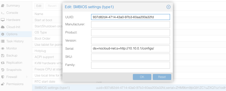
You can read the VM config from a root shell with the command qm config $ID ($ID - VM ID number of virtual machine), you will see something like:
# qm config $ID
...
smbios1: uuid=5b0f7dcf-cfe3-4bf3-87a2-1cad29bd51f9,serial=ZHM9bm9jbG91ZC1uZXQ7cz1odHRwOi8vMTAuMTAuMC4xL2NvbmZpZ3Mv,base64=1
...
Where serial holds the base64-encoded string version of ds=nocloud-net;s=http://10.10.0.1/configs/.
The serial can also be set from a root shell on the Proxmox server:
# qm set $VM --smbios1 "uuid=5b0f7dcf-cfe3-4bf3-87a2-1cad29bd51f9,serial=$(printf '%s' 'ds=nocloud-net;s=http://10.10.0.1/configs/' | base64),base64=1"
update VM 105: -smbios1 uuid=5b0f7dcf-cfe3-4bf3-87a2-1cad29bd51f9,serial=ZHM9bm9jbG91ZC1uZXQ7cz1odHRwOi8vMTAuMTAuMC4xL2NvbmZpZ3Mv,base64=1
Keep in mind that if you set the serial from the command line, you must encode it as base64, and you must include the UUID and any other settings that are already set for the smbios1 option or they will be removed.
CDROM/USB
Talos can also get machine config from local attached storage without any prior network connection being established.
You can provide configs to the server via files on a VFAT or ISO9660 filesystem.
The filesystem volume label must be cidata or CIDATA.
Example: QEMU
Create and prepare Talos machine config:
export CONTROL_PLANE_IP=192.168.1.10

talosctl gen config talos-nocloud https://$CONTROL_PLANE_IP:6443 --output-dir _out
Prepare cloud-init configs:
mkdir -p iso
mv _out/controlplane.yaml iso/user-data
echo "local-hostname: controlplane-1" > iso/meta-data
cat > iso/network-config << EOF
version: 1
config:
   - type: physical
     name: eth0
     mac_address: "52:54:00:12:34:00"
     subnets:
        - type: static
          address: 192.168.1.10
          netmask: 255.255.255.0
          gateway: 192.168.1.254
EOF
Create cloud-init iso image
cd iso && genisoimage -output cidata.iso -V cidata -r -J user-data meta-data network-config
Start the VM
qemu-system-x86_64 \
    ...
    -cdrom iso/cidata.iso \
    ...
Example: Proxmox
Proxmox can create cloud-init disk for you. Edit the cloud-init config information in Proxmox as follows, substitute your own information as necessary:
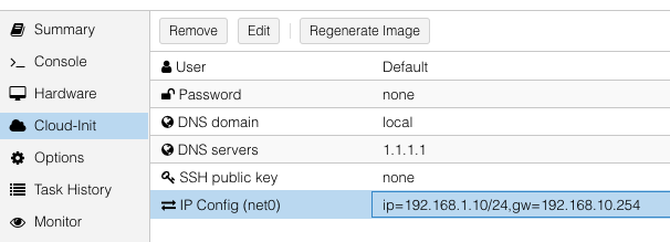
and then add a cicustom param to the virtual machine’s configuration from a root shell:
# qm set 100 --cicustom user=local:snippets/controlplane-1.yml
update VM 100: -cicustom user=local:snippets/controlplane-1.yml
Note:
snippets/controlplane-1.ymlis Talos machine config. It is usually located at/var/lib/vz/snippets/controlplane-1.yml. This file must be placed to this path manually, as Proxmox does not support snippet uploading via API/GUI.
Click on Regenerate Image button after the above changes are made.
11 - OpenStack
Creating a Cluster via the CLI
In this guide, we will create an HA Kubernetes cluster in OpenStack with 1 worker node. We will assume an existing some familiarity with OpenStack. If you need more information on OpenStack specifics, please see the official OpenStack documentation.
Environment Setup
You should have an existing openrc file. This file will provide environment variables necessary to talk to your OpenStack cloud. See here for instructions on fetching this file.
Create the Image
First, download the OpenStack image from a Talos release.
These images are called openstack-$ARCH.tar.gz.
Untar this file with tar -xvf openstack-$ARCH.tar.gz.
The resulting file will be called disk.raw.
Upload the Image
Once you have the image, you can upload to OpenStack with:
openstack image create --public --disk-format raw --file disk.raw talos
Network Infrastructure
Load Balancer and Network Ports
Once the image is prepared, you will need to work through setting up the network. Issue the following to create a load balancer, the necessary network ports for each control plane node, and associations between the two.
Creating loadbalancer:
# Create load balancer, updating vip-subnet-id if necessary
openstack loadbalancer create --name talos-control-plane --vip-subnet-id public

# Create listener
openstack loadbalancer listener create --name talos-control-plane-listener --protocol TCP --protocol-port 6443 talos-control-plane

# Pool and health monitoring
openstack loadbalancer pool create --name talos-control-plane-pool --lb-algorithm ROUND_ROBIN --listener talos-control-plane-listener --protocol TCP
openstack loadbalancer healthmonitor create --delay 5 --max-retries 4 --timeout 10 --type TCP talos-control-plane-pool
Creating ports:
# Create ports for control plane nodes, updating network name if necessary
openstack port create --network shared talos-control-plane-1
openstack port create --network shared talos-control-plane-2
openstack port create --network shared talos-control-plane-3

# Create floating IPs for the ports, so that you will have talosctl connectivity to each control plane
openstack floating ip create --port talos-control-plane-1 public
openstack floating ip create --port talos-control-plane-2 public
openstack floating ip create --port talos-control-plane-3 public
Note: Take notice of the private and public IPs associated with each of these ports, as they will be used in the next step. Additionally, take node of the port ID, as it will be used in server creation.
Associate port’s private IPs to loadbalancer:
# Create members for each port IP, updating subnet-id and address as necessary.
openstack loadbalancer member create --subnet-id shared-subnet --address <PRIVATE IP OF talos-control-plane-1 PORT> --protocol-port 6443 talos-control-plane-pool
openstack loadbalancer member create --subnet-id shared-subnet --address <PRIVATE IP OF talos-control-plane-2 PORT> --protocol-port 6443 talos-control-plane-pool
openstack loadbalancer member create --subnet-id shared-subnet --address <PRIVATE IP OF talos-control-plane-3 PORT> --protocol-port 6443 talos-control-plane-pool
Security Groups
This example uses the default security group in OpenStack. Ports have been opened to ensure that connectivity from both inside and outside the group is possible. You will want to allow, at a minimum, ports 6443 (Kubernetes API server) and 50000 (Talos API) from external sources. It is also recommended to allow communication over all ports from within the subnet.
Cluster Configuration
With our networking bits setup, we’ll fetch the IP for our load balancer and create our configuration files.
LB_PUBLIC_IP=$(openstack loadbalancer show talos-control-plane -f json | jq -r .vip_address)

talosctl gen config talos-k8s-openstack-tutorial https://${LB_PUBLIC_IP}:6443
Additionally, you can specify --config-patch with RFC6902 jsonpatch which will be applied during the config generation.
Compute Creation
We are now ready to create our OpenStack nodes.
Create control plane:
# Create control planes 2 and 3, substituting the same info.
for i in $( seq 1 3 ); do
  openstack server create talos-control-plane-$i --flavor m1.small --nic port-id=talos-control-plane-$i --image talos --user-data /path/to/controlplane.yaml
done
Create worker:
# Update network name as necessary.
openstack server create talos-worker-1 --flavor m1.small --network shared --image talos --user-data /path/to/worker.yaml
Note: This step can be repeated to add more workers.
Bootstrap Etcd
You should now be able to interact with your cluster with talosctl.
We will use one of the floating IPs we allocated earlier.
It does not matter which one.
Set the endpoints and nodes:
talosctl --talosconfig talosconfig config endpoint <control plane 1 IP>
talosctl --talosconfig talosconfig config node <control plane 1 IP>
Bootstrap etcd:
talosctl --talosconfig talosconfig bootstrap
Retrieve the kubeconfig
At this point we can retrieve the admin kubeconfig by running:
talosctl --talosconfig talosconfig kubeconfig .
12 - Oracle
Upload image
Oracle Cloud at the moment does not have a Talos official image. So you can use Bring Your Own Image (BYOI) approach.
Prepare an image for upload:
Generate an image using Image Factory.
Download the disk image artifact (e.g: https://factory.talos.dev/image/376567988ad370138ad8b2698212367b8edcb69b5fd68c80be1f2ec7d603b4ba/v1.8.0/oracle-arm64.raw.xz)
Define the image metadata file called
image_metadata.json. Example for anarm64deployment:{ "version": 2, "externalLaunchOptions": { "firmware": "UEFI_64", "networkType": "PARAVIRTUALIZED", "bootVolumeType": "PARAVIRTUALIZED", "remoteDataVolumeType": "PARAVIRTUALIZED", "localDataVolumeType": "PARAVIRTUALIZED", "launchOptionsSource": "PARAVIRTUALIZED", "pvAttachmentVersion": 2, "pvEncryptionInTransitEnabled": true, "consistentVolumeNamingEnabled": true }, "imageCapabilityData": null, "imageCapsFormatVersion": null, "operatingSystem": "Talos", "operatingSystemVersion": "1.7.6", "additionalMetadata": { "shapeCompatibilities": [ { "internalShapeName": "VM.Standard.A1.Flex", "ocpuConstraints": null, "memoryConstraints": null } ] } }Extract the xz or zst archive:
xz --decompress ./oracle-arm64.raw.xz

# or

zstd --decompress ./oracle-arm64.raw.zst
Convert the image to a
qcow2format (using qemu):qemu-img convert -f raw -O qcow2 oracle-arm64.raw oracle-arm64.qcow2Create an archive containing the image and metadata called
talos-oracle-arm64.oci:tar zcf oracle-arm64.oci oracle-arm64.qcow2 image_metadata.jsonUpload the image to a storage bucket.
Create an image, using the new URL format for the storage bucket object.
Note: file names depends on configuration of deployment such as architecture, adjust accordingly.
Talos config
OracleCloud has highly available NTP service, it can be enabled in Talos machine config with:
machine:
  time:
    servers:
      - 169.254.169.254
Creating a Cluster via the CLI
Login to the console. And open the Cloud Shell.
Create a network
export cidr_block=10.0.0.0/16
export subnet_block=10.0.0.0/24
export compartment_id=<substitute-value-of-compartment_id> # https://docs.cloud.oracle.com/en-us/iaas/tools/oci-cli/latest/oci_cli_docs/cmdref/network/vcn/create.html#cmdoption-compartment-id

export vcn_id=$(oci network vcn create --cidr-block $cidr_block --display-name talos-example --compartment-id $compartment_id --query data.id --raw-output)
export rt_id=$(oci network subnet create --cidr-block $subnet_block --display-name kubernetes --compartment-id $compartment_id --vcn-id $vcn_id --query data.route-table-id --raw-output)
export ig_id=$(oci network internet-gateway create --compartment-id $compartment_id --is-enabled true --vcn-id $vcn_id --query data.id --raw-output)

oci network route-table update --rt-id $rt_id --route-rules "[{\"cidrBlock\":\"0.0.0.0/0\",\"networkEntityId\":\"$ig_id\"}]" --force

# disable firewall
export sl_id=$(oci network vcn list --compartment-id $compartment_id --query 'data[0]."default-security-list-id"' --raw-output)

oci network security-list update --security-list-id $sl_id --egress-security-rules '[{"destination": "0.0.0.0/0", "protocol": "all", "isStateless": false}]' --ingress-security-rules '[{"source": "0.0.0.0/0", "protocol": "all", "isStateless": false}]' --force
Create a Load Balancer
Create a load balancer by issuing the commands shown below. Save the IP/DNS name, as this info will be used in the next step.
export subnet_id=$(oci network subnet list --compartment-id=$compartment_id --display-name kubernetes --query data[0].id --raw-output)
export network_load_balancer_id=$(oci nlb network-load-balancer create --compartment-id $compartment_id --display-name controlplane-lb --subnet-id $subnet_id --is-preserve-source-destination false --is-private false --query data.id --raw-output)

cat <<EOF > talos-health-checker.json
{
  "intervalInMillis": 10000,
  "port": 50000,
  "protocol": "TCP"
}
EOF

oci nlb backend-set create --health-checker file://talos-health-checker.json --name talos --network-load-balancer-id $network_load_balancer_id --policy TWO_TUPLE --is-preserve-source false
oci nlb listener create --default-backend-set-name talos --name talos --network-load-balancer-id $network_load_balancer_id --port 50000 --protocol TCP

cat <<EOF > controlplane-health-checker.json
{
  "intervalInMillis": 10000,
  "port": 6443,
  "protocol": "HTTPS",
  "returnCode": 401,
  "urlPath": "/readyz"
}
EOF

oci nlb backend-set create --health-checker file://controlplane-health-checker.json --name controlplane --network-load-balancer-id $network_load_balancer_id --policy TWO_TUPLE --is-preserve-source false
oci nlb listener create --default-backend-set-name controlplane --name controlplane --network-load-balancer-id $network_load_balancer_id --port 6443 --protocol TCP

# Save the external IP
oci nlb network-load-balancer list --compartment-id $compartment_id --display-name controlplane-lb --query 'data.items[0]."ip-addresses"'
Create the Machine Configuration Files
Generating Base Configurations
Using the IP/DNS name of the loadbalancer created earlier, generate the base configuration files for the Talos machines by issuing:
$ talosctl gen config talos-k8s-oracle-tutorial https://<load balancer IP or DNS>:6443 --additional-sans <load balancer IP or DNS>
created controlplane.yaml
created worker.yaml
created talosconfig
At this point, you can modify the generated configs to your liking.
Optionally, you can specify --config-patch with RFC6902 jsonpatches which will be applied during the config generation.
Validate the Configuration Files
Validate any edited machine configs with:
$ talosctl validate --config controlplane.yaml --mode cloud
controlplane.yaml is valid for cloud mode
$ talosctl validate --config worker.yaml --mode cloud
worker.yaml is valid for cloud mode
Create the Servers
Create the Control Plane Nodes
Create the control plane nodes with:
export shape='VM.Standard.A1.Flex'
export subnet_id=$(oci network subnet list --compartment-id=$compartment_id --display-name kubernetes --query data[0].id --raw-output)
export image_id=$(oci compute image list --compartment-id $compartment_id --shape $shape --operating-system Talos --limit 1 --query data[0].id --raw-output)
export availability_domain=$(oci iam availability-domain list --compartment-id=$compartment_id --query data[0].name --raw-output)
export network_load_balancer_id=$(oci nlb network-load-balancer list --compartment-id $compartment_id --display-name controlplane-lb --query 'data.items[0].id' --raw-output)

cat <<EOF > shape.json
{
  "memoryInGBs": 4,
  "ocpus": 1
}
EOF

export instance_id=$(oci compute instance launch --shape $shape --shape-config file://shape.json --availability-domain $availability_domain --compartment-id $compartment_id --image-id $image_id --subnet-id $subnet_id --display-name controlplane-1 --private-ip 10.0.0.11 --assign-public-ip true --launch-options '{"networkType":"PARAVIRTUALIZED"}' --user-data-file controlplane.yaml --query 'data.id' --raw-output)

oci nlb backend create --backend-set-name talos --network-load-balancer-id $network_load_balancer_id --port 50000 --target-id $instance_id
oci nlb backend create --backend-set-name controlplane --network-load-balancer-id $network_load_balancer_id --port 6443 --target-id $instance_id

export instance_id=$(oci compute instance launch --shape $shape --shape-config file://shape.json --availability-domain $availability_domain --compartment-id $compartment_id --image-id $image_id --subnet-id $subnet_id --display-name controlplane-2 --private-ip 10.0.0.12 --assign-public-ip true --launch-options '{"networkType":"PARAVIRTUALIZED"}' --user-data-file controlplane.yaml --query 'data.id' --raw-output)

oci nlb backend create --backend-set-name talos --network-load-balancer-id $network_load_balancer_id --port 50000 --target-id $instance_id
oci nlb backend create --backend-set-name controlplane --network-load-balancer-id $network_load_balancer_id --port 6443 --target-id $instance_id

export instance_id=$(oci compute instance launch --shape $shape --shape-config file://shape.json --availability-domain $availability_domain --compartment-id $compartment_id --image-id $image_id --subnet-id $subnet_id --display-name controlplane-3 --private-ip 10.0.0.13 --assign-public-ip true --launch-options '{"networkType":"PARAVIRTUALIZED"}' --user-data-file controlplane.yaml --query 'data.id' --raw-output)

oci nlb backend create --backend-set-name talos --network-load-balancer-id $network_load_balancer_id --port 50000 --target-id $instance_id
oci nlb backend create --backend-set-name controlplane --network-load-balancer-id $network_load_balancer_id --port 6443 --target-id $instance_id
Create the Worker Nodes
Create the worker nodes with the following command, repeating (and incrementing the name counter) as many times as desired.
export subnet_id=$(oci network subnet list --compartment-id=$compartment_id --display-name kubernetes --query data[0].id --raw-output)
export image_id=$(oci compute image list --compartment-id $compartment_id --operating-system Talos --limit 1 --query data[0].id --raw-output)
export availability_domain=$(oci iam availability-domain list --compartment-id=$compartment_id --query data[0].name --raw-output)
export shape='VM.Standard.E2.1.Micro'

oci compute instance launch --shape $shape --availability-domain $availability_domain --compartment-id $compartment_id --image-id $image_id --subnet-id $subnet_id --display-name worker-1 --assign-public-ip true --user-data-file worker.yaml

oci compute instance launch --shape $shape --availability-domain $availability_domain --compartment-id $compartment_id --image-id $image_id --subnet-id $subnet_id --display-name worker-2 --assign-public-ip true --user-data-file worker.yaml

oci compute instance launch --shape $shape --availability-domain $availability_domain --compartment-id $compartment_id --image-id $image_id --subnet-id $subnet_id --display-name worker-3 --assign-public-ip true --user-data-file worker.yaml
Bootstrap Etcd
To configure talosctl we will need the first control plane node’s IP.
This can be found by issuing:
export instance_id=$(oci compute instance list --compartment-id $compartment_id --display-name controlplane-1 --query 'data[0].id' --raw-output)

oci compute instance list-vnics --instance-id $instance_id --query 'data[0]."private-ip"' --raw-output
Set the endpoints and nodes for your talosconfig with:
talosctl --talosconfig talosconfig config endpoint <load balancer IP or DNS>
talosctl --talosconfig talosconfig config node <control-plane-1-IP>
Bootstrap etcd on the first control plane node with:
talosctl --talosconfig talosconfig bootstrap
Retrieve the kubeconfig
At this point we can retrieve the admin kubeconfig by running:
talosctl --talosconfig talosconfig kubeconfig .
13 - Scaleway
Talos is known to work on scaleway.com; however, it is currently undocumented.
14 - UpCloud
In this guide we will create an HA Kubernetes cluster 3 control plane nodes and 1 worker node. We assume some familiarity with UpCloud. If you need more information on UpCloud specifics, please see the official UpCloud documentation.
Create the Image
The best way to create an image for UpCloud, is to build one using
Hashicorp packer, with the
upcloud-amd64.raw.xz image found on the Talos Releases.
Using the general ISO is also possible, but the UpCloud image has some UpCloud
specific features implemented, such as the fetching of metadata and user data to configure the nodes.
To create the cluster, you need a few things locally installed:
NOTE: Make sure your account allows API connections. To do so, log into UpCloud control panel and go to People -> Account -> Permissions -> Allow API connections checkbox. It is recommended to create a separate subaccount for your API access and only set the API permission.
To use the UpCloud CLI, you need to create a config in $HOME/.config/upctl.yaml
username: your_upcloud_username
password: your_upcloud_password
To use the UpCloud packer plugin, you need to also export these credentials to your
environment variables, by e.g. putting the following in your .bashrc or .zshrc
export UPCLOUD_USERNAME="<username>"
export UPCLOUD_PASSWORD="<password>"
Next create a config file for packer to use:
# upcloud.pkr.hcl

packer {
  required_plugins {
    upcloud = {
      version = ">=v1.0.0"
      source  = "github.com/UpCloudLtd/upcloud"
    }
  }
}

variable "talos_version" {
  type    = string
  default = "v1.8.0"
}

locals {
  image = "https://factory.talos.dev/image/376567988ad370138ad8b2698212367b8edcb69b5fd68c80be1f2ec7d603b4ba/${var.talos_version}/upcloud-amd64.raw.xz"
}

variable "username" {
  type        = string
  description = "UpCloud API username"
  default     = "${env("UPCLOUD_USERNAME")}"
}

variable "password" {
  type        = string
  description = "UpCloud API password"
  default     = "${env("UPCLOUD_PASSWORD")}"
  sensitive   = true
}

source "upcloud" "talos" {
  username        = "${var.username}"
  password        = "${var.password}"
  zone            = "us-nyc1"
  storage_name    = "Debian GNU/Linux 11 (Bullseye)"
  template_name   = "Talos (${var.talos_version})"
}

build {
  sources = ["source.upcloud.talos"]

  provisioner "shell" {
    inline = [
      "apt-get install -y wget xz-utils",
      "wget -q -O /tmp/talos.raw.xz ${local.image}",
      "xz -d -c /tmp/talos.raw.xz | dd of=/dev/vda",
    ]
  }

  provisioner "shell-local" {
      inline = [
      "upctl server stop --type hard custom",
      ]
  }
}
Now create a new image by issuing the commands shown below.
packer init .
packer build .
After doing this, you can find the custom image in the console interface under storage.
Creating a Cluster via the CLI
Create an Endpoint
To communicate with the Talos cluster you will need a single endpoint that is used to access the cluster. This can either be a loadbalancer that will sit in front of all your control plane nodes, a DNS name with one or more A or AAAA records pointing to the control plane nodes, or directly the IP of a control plane node.
Which option is best for you will depend on your needs. Endpoint selection has been further documented here.
After you decide on which endpoint to use, note down the domain name or IP, as we will need it in the next step.
Create the Machine Configuration Files
Generating Base Configurations
Using the DNS name of the endpoint created earlier, generate the base configuration files for the Talos machines:
$ talosctl gen config talos-upcloud-tutorial https://<load balancer IP or DNS>:<port> --install-disk /dev/vda
created controlplane.yaml
created worker.yaml
created talosconfig
At this point, you can modify the generated configs to your liking. Depending on the Kubernetes version you want to run, you might need to select a different Talos version, as not all versions are compatible. You can find the support matrix here.
Optionally, you can specify --config-patch with RFC6902 jsonpatch or yamlpatch
which will be applied during the config generation.
Validate the Configuration Files
$ talosctl validate --config controlplane.yaml --mode cloud
controlplane.yaml is valid for cloud mode
$ talosctl validate --config worker.yaml --mode cloud
worker.yaml is valid for cloud mode
Create the Servers
Create the Control Plane Nodes
Run the following to create three total control plane nodes:
for ID in $(seq 3); do
    upctl server create \
      --zone us-nyc1 \
      --title talos-us-nyc1-master-$ID \
      --hostname talos-us-nyc1-master-$ID \
      --plan 2xCPU-4GB \
      --os "Talos (v1.8.0)" \
      --user-data "$(cat controlplane.yaml)" \
      --enable-metada
done
Note: modify the zone and OS depending on your preferences. The OS should match the template name generated with packer in the previous step.
Note the IP address of the first control plane node, as we will need it later.
Create the Worker Nodes
Run the following to create a worker node:
upctl server create \
  --zone us-nyc1 \
  --title talos-us-nyc1-worker-1 \
  --hostname talos-us-nyc1-worker-1 \
  --plan 2xCPU-4GB \
  --os "Talos (v1.8.0)" \
  --user-data "$(cat worker.yaml)" \
  --enable-metada
Bootstrap Etcd
To configure talosctl we will need the first control plane node’s IP, as noted earlier.
We only add one node IP, as that is the entry into our cluster against which our commands will be run.
All requests to other nodes are proxied through the endpoint, and therefore not
all nodes need to be manually added to the config.
You don’t want to run your commands against all nodes, as this can destroy your
cluster if you are not careful (further documentation).
Set the endpoints and nodes:
talosctl --talosconfig talosconfig config endpoint <control plane 1 IP>
talosctl --talosconfig talosconfig config node <control plane 1 IP>
Bootstrap etcd:
talosctl --talosconfig talosconfig bootstrap
Retrieve the kubeconfig
At this point we can retrieve the admin kubeconfig by running:
talosctl --talosconfig talosconfig kubeconfig
It will take a few minutes before Kubernetes has been fully bootstrapped, and is accessible.
You can check if the nodes are registered in Talos by running
talosctl --talosconfig talosconfig get members
To check if your nodes are ready, run
kubectl get nodes
15 - Vultr
Creating a Cluster using the Vultr CLI
This guide will demonstrate how to create a highly-available Kubernetes cluster with one worker using the Vultr cloud provider.
Vultr have a very well documented REST API, and an open-source CLI tool to interact with the API which will be used in this guide.
Make sure to follow installation and authentication instructions for the vultr-cli tool.
Boot Options
Upload an ISO Image
First step is to make the Talos ISO available to Vultr by uploading the latest release of the ISO to the Vultr ISO server.
vultr-cli iso create --url https://factory.talos.dev/image/376567988ad370138ad8b2698212367b8edcb69b5fd68c80be1f2ec7d603b4ba/v1.8.0vultr-amd64.iso
Make a note of the ID in the output, it will be needed later when creating the instances.met
PXE Booting via Image Factory
Talos Linux can be PXE-booted on Vultr using Image Factory, using the vultr platform: e.g.
https://pxe.factory.talos.dev/pxe/376567988ad370138ad8b2698212367b8edcb69b5fd68c80be1f2ec7d603b4ba/v1.8.0/vultr-amd64 (this URL references the default schematic and amd64 architecture).
Make a note of the ID in the output, it will be needed later when creating the instances.
Create a Load Balancer
A load balancer is needed to serve as the Kubernetes endpoint for the cluster.
vultr-cli load-balancer create \
   --region $REGION \
   --label "Talos Kubernetes Endpoint" \
   --port 6443 \
   --protocol tcp \
   --check-interval 10 \
   --response-timeout 5 \
   --healthy-threshold 5 \
   --unhealthy-threshold 3 \
   --forwarding-rules frontend_protocol:tcp,frontend_port:443,backend_protocol:tcp,backend_port:6443
Make a note of the ID of the load balancer from the output of the above command, it will be needed after the control plane instances are created.
vultr-cli load-balancer get $LOAD_BALANCER_ID | grep ^IP
Make a note of the IP address, it will be needed later when generating the configuration.
Create the Machine Configuration
Generate Base Configuration
Using the IP address (or DNS name if one was created) of the load balancer created above, generate the machine configuration files for the new cluster.
talosctl gen config talos-kubernetes-vultr https://$LOAD_BALANCER_ADDRESS
Once generated, the machine configuration can be modified as necessary for the new cluster, for instance updating disk installation, or adding SANs for the certificates.
Validate the Configuration Files
talosctl validate --config controlplane.yaml --mode cloud
talosctl validate --config worker.yaml --mode cloud
Create the Nodes
Create the Control Plane Nodes
First a control plane needs to be created, with the example below creating 3 instances in a loop.
The instance type (noted by the --plan vc2-2c-4gb argument) in the example is for a minimum-spec control plane node, and should be updated to suit the cluster being created.
for id in $(seq 3); do
    vultr-cli instance create \
        --plan vc2-2c-4gb \
        --region $REGION \
        --iso $TALOS_ISO_ID \
        --host talos-k8s-cp${id} \
        --label "Talos Kubernetes Control Plane" \
        --tags talos,kubernetes,control-plane
done
Make a note of the instance IDs, as they are needed to attach to the load balancer created earlier.
vultr-cli load-balancer update $LOAD_BALANCER_ID --instances $CONTROL_PLANE_1_ID,$CONTROL_PLANE_2_ID,$CONTROL_PLANE_3_ID
Once the nodes are booted and waiting in maintenance mode, the machine configuration can be applied to each one in turn.
talosctl --talosconfig talosconfig apply-config --insecure --nodes $CONTROL_PLANE_1_ADDRESS --file controlplane.yaml
talosctl --talosconfig talosconfig apply-config --insecure --nodes $CONTROL_PLANE_2_ADDRESS --file controlplane.yaml
talosctl --talosconfig talosconfig apply-config --insecure --nodes $CONTROL_PLANE_3_ADDRESS --file controlplane.yaml
Create the Worker Nodes
Now worker nodes can be created and configured in a similar way to the control plane nodes, the difference being mainly in the machine configuration file.
Note that like with the control plane nodes, the instance type (here set by --plan vc2-1-1gb) should be changed for the actual cluster requirements.
for id in $(seq 1); do
    vultr-cli instance create \
        --plan vc2-1c-1gb \
        --region $REGION \
        --iso $TALOS_ISO_ID \
        --host talos-k8s-worker${id} \
        --label "Talos Kubernetes Worker" \
        --tags talos,kubernetes,worker
done
Once the worker is booted and in maintenance mode, the machine configuration can be applied in the following manner.
talosctl --talosconfig talosconfig apply-config --insecure --nodes $WORKER_1_ADDRESS --file worker.yaml
Bootstrap etcd
Once all the cluster nodes are correctly configured, the cluster can be bootstrapped to become functional.
It is important that the talosctl bootstrap command be executed only once and against only a single control plane node.
talosctl --talosconfig talosconfig bootstrap --endpoints $CONTROL_PLANE_1_ADDRESS --nodes $CONTROL_PLANE_1_ADDRESS
Configure Endpoints and Nodes
While the cluster goes through the bootstrapping process and beings to self-manage, the talosconfig can be updated with the endpoints and nodes.
talosctl --talosconfig talosconfig config endpoints $CONTROL_PLANE_1_ADDRESS $CONTROL_PLANE_2_ADDRESS $CONTROL_PLANE_3_ADDRESS
talosctl --talosconfig talosconfig config nodes $CONTROL_PLANE_1_ADDRESS $CONTROL_PLANE_2_ADDRESS $CONTROL_PLANE_3_ADDRESS WORKER_1_ADDRESS
Retrieve the kubeconfig
Finally, with the cluster fully running, the administrative kubeconfig can be retrieved from the Talos API to be saved locally.
talosctl --talosconfig talosconfig kubeconfig .
Now the kubeconfig can be used by any of the usual Kubernetes tools to interact with the Talos-based Kubernetes cluster as normal.